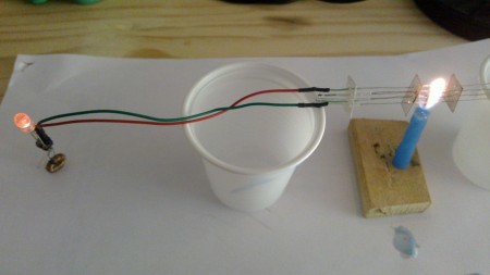
This is just a small project that I’ve been doing to explore some not so well known technologies. The goal is simple: use the heat of a candle to turn on an LED. Actually making a device that does this function turned out to be not that simple, though.
Part 1: The Thermopile
To generate electricity out of a candle flame, I decided not to go the obvious route of buying a TEG, but instead to try building its ancestor, the thermopile.
A TEG, or thermoelectric generator is a device made of a number of semiconductor junctions in series that generate a small voltage when a temperature difference is applied to them. They are essentially the same in construction as the more common TEC, or thermoelectric cooler, that can be found easily on ebay.
The main reason why I have decided not to use them, is that TECs/TEGs get damaged at temperatures above 150°C or so. Since the flame of a candle is well above that temperature, I would need to come up with a way to reduce the flame temperature to a usable value.
A thermopile is a series arrangement of thermocouples. It works in the same way as a TEG, but uses metal junctions instead of semiconductor ones. Thus, it is more rugged and can easily withstand higher temperatures.
At first, I tried making a thermocouple out of materials I had at home, namely copper wire and nichrome wire, but the results were very poor, as I could only get a few millivolts out of it when exposed to a flame. So, I ordered a K thermocouple to cut its wires into pieces and experiment with thermopiles.
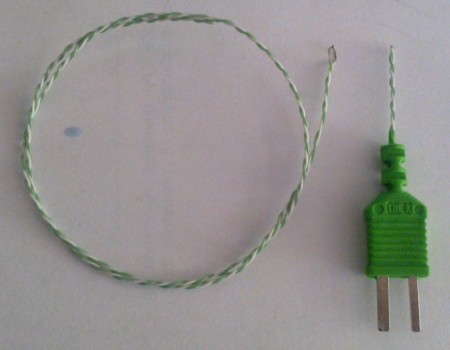
This is what remains of the thermocouple after the experiments. I’m sure it still works if I solder back the wires to the connector.
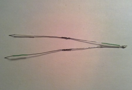
This is my first thermopile. It was built by cutting two 4cm pieces of thermocouple cable, straightening the wires -as they were twisted together- stripping the insulation and twisting the chromel and alumel in order to make the hot junction. I would have tried welding them together, but I lack the necessary equipment. The cold junction between the two thermocouples can simply be soldered, as it doesn’t have to withstand hundred of degrees.
When exposing both hot junctions to a candle flame, I got around 65mV, that’s promising.
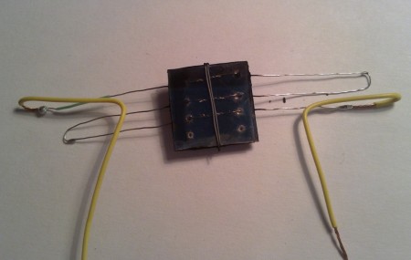
This is my second attempt at making a thermopile. I used mica sheets above and below to provide some mechanical strength and try protecting the twisted hot junctions from the flame. My fear was that since the metal is just twisted and not welded, if it oxidizes due to the heat, it may no longer form an electrical connection.
This design turned out to be a bad idea, though. Despite having three thermocouples in series, I could not get more than 50mV out of it. The main reason is most likely that the mica introduces a thermal resistance between the flame and the junctions, so the temperature they reach is lower.
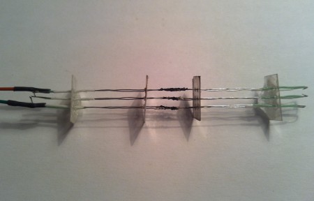
After the failed attempt, it was clear that to work well a thermopile requires the metal to be exposed to the flame. Having learned that, the next step was to make a working device and not just a test. I wanted to get around 200mV out of it (see the next part for the reason), so that means 6 thermocouples in series. After spending some time thinking how I could make a design with 6 thermocouples close together enough to be heated directly by a single candle flame, this is what came out. I used four mica spacers to prevent shorting, and epoxy on the outer spacers to provide some mechanical robustness to the design.
I also tried to do some computations to figure out what could be expected out of such a device. The expected voltage is three times the one I got out of the first test, about 200mV. That means around 33mV per thermocouple.
Estimating the current is a little bit more difficult. The seebeck effect theory seems to focus on a voltage difference being generated, but does not mention current. So I guessed that what limits the current flow is just the resistance of the wires. Looking up the resistivity of chromel and alumel resulted in those formulas:
chromel 0.706uohm/m (1+0.00032*T)
alumel 0.294uohm/m (1+0.00239*T)
The resistance depends on temperature, and given that the hot junction reaches hundred of degrees, it likely can’t be neglected.
According to the K thermocouple curves, a 33mV voltage means around 700°C of temperature difference. As the cold junction does get a little bit hot as well, an educated guess may be 750°C for the hot junction, and 50°C for the cold one. To simplify computations, I assumed that temperature varies linearly along the wire, leading to an average temperature of 400°C. Considering that the wires have a 0.3mm diameter, and are 4.5cm long, a single thermocouple has an estimated resistance of 0.9ohm, and the entire arrangement 5.4ohm.
This means a 37mA short circuit current. The maximum power that can be expected out of this device is thus half of the open circuit voltage times the short circuit current, or around 3.7mW.
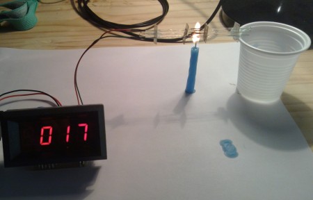
Measuring the short circuit current of a device outputting such a low voltage is not easy. A simple multimeter has a burden voltage in the same order of magnitude as the open circuit voltage (~200mV), introducing a significant error in the measure. As I don’t have a uCurrent, I settled for using a short loop of 26AWG copper wire as a low value shunt resistance, and using a millivoltmeter with 0.1mV resolution. Since the resistance of the shunt is unknown, it was first measured using a known current, and resulted to be 0.035ohm.
In the picture above we can see the reading, which is 1.7mV (the millivoltmeter lacks a decimal point). The short circuit current is 48mA, nearly 10mA higher then predicted. This was due to the wire having a lower resistance than the one computed before.
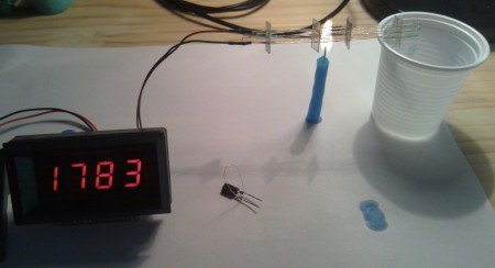
An open circuit test showed I got 178mV out of it. Not quite 200mV as I hoped, but close enough. In the picture you can also see the wire loop used as low value shunt resistor. So, with ~180mV open circuit and ~48mA short circuit, assuming the best power transfer to the load, this thermopile would produce around 4.3mW.
Part 2: DC-DC converter
Up until know I had fun building a working thermopile, but how to turn on an LED with it? LEDs need different voltages to turn on, with red ones requiring just 1.8V, and blue ones going as high as 3.6V. Thus, at least 55 thermocouples in series are required to directly power an LED. A different approach is apparently required.
The issue is, there aren’t many ways to build a DC-DC converter that works with just a few hundred millivolts. A blocking oscillator, also commonly known as joule thief can be designed to operate at just 200mV, if using a transistor with a low enough VCE|sat, but still requires 700mV to bias the base when first powered up. MOSFETS are even worse, even the best ones require more than 1V to their gate before thay do anything.
Although there are energy harvesting ICs nowadays that are designed to step up very low voltages, I didn’t want to go the IC route. Given the experimental nature of this project, I wanted to stay close to physics rather than using a black box IC that does what I need but leaves me with little knowledge of what’s going on inside. Also, I didn’t happen to have any energy harvesting IC lying around, but I had something else that would do the trick.
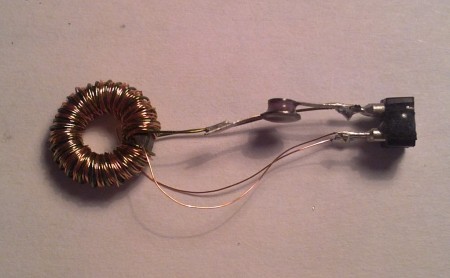
A while ago I watched a video about tunnel diodes. They are quite unlike conventional diodes, as for voltages between around 0.18V and 0.8V they have a negative resistance region, where current decreases as voltage increases. This means that an oscillator can be made with them, operating at just 180mV. From there, a transformer can be used to step up the voltage. An inverter circuit can thus be made with just two components: a tunnel diode and a transformer. Such a circuit appears to be little known, but is very old. I found it at page 104 in this RCA book from 1963.
The tunnel diodes I have are АИ301Г, rated at 10mA peak current. For the transformer, I repurposed a toroidal core out of a broken CFL neon lamp. I measured the inductance factor in order to get predictable inductance values, and it is AL=700nH. I wanted the device to oscillate at just a few tens of kilohertz, so the primary was chosen to have a rather high 500uH inductance. Doing the math, 27 turns are needed. I used 30AWG wire. The secondary was made out of 95 turns of AWG36 wire.
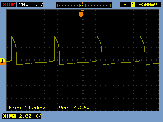
This is the output of the secondary. 4.5V peaks at 15KHz.
Yes, it does turn on a high brightness LED. Success.
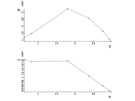
To characterize a bit more the output, I rectified the secondary of the transformer with a BAT42 diode and a 1uF capacitor. Applying different load resistors, here are the curves of the output. The maximum power point is 180uA at 1.8V, or 324uW. Quite a bit lower than expected. This is most likely because the thermopile voltage is only 180mV, which is the same as the tunnel diode peak voltage. So, the oscillator barely turns on. With 250 to 300mV the power output would probably be higher. Also, a disadvantage of the tunnel diode oscillator is that the maximum output power is limited by the diode peak current, which is just 10mA. To get more power, you need a bigger diode.
Conclusions
Here’s a video of the thermopile working.
The experiment was a success. Maybe someday I’ll try to improve the efficiency by making a 8 element thermopile, but still I’ll be limited by the tunnel diode peak current. Despite the RCA book mentions 1, 10 and even 100A tunnel diodes, those 10mA diodes were the best I could find. Maybe I could try a push-pull configuration with two tunnel diodes, or use the tunnel diode to kickstart a joule thief, who knows.
March 31, 2016 at 1:01 am |
[…] has an interesting project that combines two of those intriguing textbook references, he’s created a thermopile that lights an LED through an inverter whose oscillator is a tunnel …. Dig out the […]
March 31, 2016 at 1:06 am |
[…] has an interesting project that combines two of those intriguing textbook references, he’s created a thermopile that lights an LED through an inverter whose oscillator is a tunnel …. Dig out the […]
March 31, 2016 at 1:32 am |
[…] has an interesting project that combines two of those intriguing textbook references, he’s created a thermopile that lights an LED through an inverter whose oscillator is a tunnel …. Dig out the […]
March 31, 2016 at 3:30 am |
[…] has an interesting project that combines two of those intriguing textbook references, he’s created a thermopile that lights an LED through an inverter whose oscillator is a tunnel …. Dig out the […]
March 31, 2016 at 9:16 am |
[…] has an interesting project that combines two of those intriguing textbook references, he’s created a thermopile that lights an LED through an inverter whose oscillator is a tunnel diod…. Dig out the […]