Archive for the ‘Projects’ Category

Thermopiles and tunnel diodes: a candle powered LED

March 25, 2016

This is just a small project that I’ve been doing to explore some not so well known technologies. The goal is simple: use the heat of a candle to turn on an LED. Actually making a device that does this function turned out to be not that simple, though.

Part 1: The Thermopile

To generate electricity out of a candle flame, I decided not to go the obvious route of buying a TEG, but instead to try building its ancestor, the thermopile.
A TEG, or thermoelectric generator is a device made of a number of semiconductor junctions in series that generate a small voltage when a temperature difference is applied to them. They are essentially the same in construction as the more common TEC, or thermoelectric cooler, that can be found easily on ebay.
The main reason why I have decided not to use them, is that TECs/TEGs get damaged at temperatures above 150°C or so. Since the flame of a candle is well above that temperature, I would need to come up with a way to reduce the flame temperature to a usable value.
A thermopile is a series arrangement of thermocouples. It works in the same way as a TEG, but uses metal junctions instead of semiconductor ones. Thus, it is more rugged and can easily withstand higher temperatures.
At first, I tried making a thermocouple out of materials I had at home, namely copper wire and nichrome wire, but the results were very poor, as I could only get a few millivolts out of it when exposed to a flame. So, I ordered a K thermocouple to cut its wires into pieces and experiment with thermopiles.

00-thermocouple

This is what remains of the thermocouple after the experiments. I’m sure it still works if I solder back the wires to the connector.

01-first-thermopile

This is my first thermopile. It was built by cutting two 4cm pieces of thermocouple cable, straightening the wires -as they were twisted together- stripping the insulation and twisting the chromel and alumel in order to make the hot junction. I would have tried welding them together, but I lack the necessary equipment. The cold junction between the two thermocouples can simply be soldered, as it doesn’t have to withstand hundred of degrees.
When exposing both hot junctions to a candle flame, I got around 65mV, that’s promising.

02-second-thermopile

This is my second attempt at making a thermopile. I used mica sheets above and below to provide some mechanical strength and try protecting the twisted hot junctions from the flame. My fear was that since the metal is just twisted and not welded, if it oxidizes due to the heat, it may no longer form an electrical connection.
This design turned out to be a bad idea, though. Despite having three thermocouples in series, I could not get more than 50mV out of it. The main reason is most likely that the mica introduces a thermal resistance between the flame and the junctions, so the temperature they reach is lower.

04-third-thermopile

After the failed attempt, it was clear that to work well a thermopile requires the metal to be exposed to the flame. Having learned that, the next step was to make a working device and not just a test. I wanted to get around 200mV out of it (see the next part for the reason), so that means 6 thermocouples in series. After spending some time thinking how I could make a design with 6 thermocouples close together enough to be heated directly by a single candle flame, this is what came out. I used four mica spacers to prevent shorting, and epoxy on the outer spacers to provide some mechanical robustness to the design.

I also tried to do some computations to figure out what could be expected out of such a device. The expected voltage is three times the one I got out of the first test, about 200mV. That means around 33mV per thermocouple.
Estimating the current is a little bit more difficult. The seebeck effect theory seems to focus on a voltage difference being generated, but does not mention current. So I guessed that what limits the current flow is just the resistance of the wires. Looking up the resistivity of chromel and alumel resulted in those formulas:
chromel 0.706uohm/m (1+0.00032*T)
alumel  0.294uohm/m (1+0.00239*T)
The resistance depends on temperature, and given that the hot junction reaches hundred of degrees, it likely can’t be neglected.
According to the K thermocouple curves, a 33mV voltage means around 700°C of temperature difference. As the cold junction does get a little bit hot as well, an educated guess may be 750°C for the hot junction, and 50°C for the cold one. To simplify computations, I assumed that temperature varies linearly along the wire, leading to an average temperature of 400°C. Considering that the wires have a 0.3mm diameter, and are 4.5cm long, a single thermocouple has an estimated resistance of 0.9ohm, and the entire arrangement 5.4ohm.
This means a 37mA short circuit current. The maximum power that can be expected out of this device is thus half of the open circuit voltage times the short circuit current, or around 3.7mW.

05-short-circuit-current

Measuring the short circuit current of a device outputting such a low voltage is not easy. A simple multimeter has a burden voltage in the same order of magnitude as the open circuit voltage (~200mV), introducing a significant error in the measure. As I don’t have a uCurrent, I settled for using a short loop of 26AWG copper wire as a low value shunt resistance, and using a millivoltmeter with 0.1mV resolution. Since the resistance of the shunt is unknown, it was first measured using a known current, and resulted to be 0.035ohm.
In the picture above we can see the reading, which is 1.7mV (the millivoltmeter lacks a decimal point). The short circuit current is 48mA, nearly 10mA higher then predicted. This was due to the wire having a lower resistance than the one computed before.

06-open-circuit-voltage

An open circuit test showed I got 178mV out of it. Not quite 200mV as I hoped, but close enough. In the picture you can also see the wire loop used as low value shunt resistor. So, with ~180mV open circuit and ~48mA short circuit, assuming the best power transfer to the load, this thermopile would produce around 4.3mW.

Part 2: DC-DC converter

Up until know I had fun building a working thermopile, but how to turn on an LED with it? LEDs need different voltages to turn on, with red ones requiring just 1.8V, and blue ones going as high as 3.6V. Thus, at least 55 thermocouples in series are required to directly power an LED. A different approach is apparently required.

The issue is, there aren’t many ways to build a DC-DC converter that works with just a few hundred millivolts. A blocking oscillator, also commonly known as joule thief can be designed to operate at just 200mV, if using a transistor with a low enough VCE|sat, but still requires 700mV to bias the base when first powered up. MOSFETS are even worse, even the best ones require more than 1V to their gate before thay do anything.

Although there are energy harvesting ICs nowadays that are designed to step up very low voltages, I didn’t want to go the IC route. Given the experimental nature of this project, I wanted to stay close to physics rather than using a black box IC that does what I need but leaves me with little knowledge of what’s going on inside. Also, I didn’t happen to have any energy harvesting IC lying around, but I had something else that would do the trick.

A while ago I watched a video about tunnel diodes. They are quite unlike conventional diodes, as for voltages between around 0.18V and 0.8V they have a negative resistance region, where current decreases as voltage increases. This means that an oscillator can be made with them, operating at just 180mV. From there, a transformer can be used to step up the voltage. An inverter circuit can thus be made with just two components: a tunnel diode and a transformer. Such a circuit appears to be little known, but is very old. I found it at page 104 in this RCA book from 1963.

07-dc-dc-converter

The tunnel diodes I have are АИ301Г, rated at 10mA peak current. For the transformer, I repurposed a toroidal core out of a broken CFL neon lamp. I measured the inductance factor in order to get predictable inductance values, and it is AL=700nH. I wanted the device to oscillate at just a few tens of kilohertz, so the primary was chosen to have a rather high 500uH inductance. Doing the math, 27 turns are needed. I used 30AWG wire. The secondary was made out of 95 turns of AWG36 wire.

waveforms

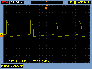
This is the output of the secondary. 4.5V peaks at 15KHz.

08-working.jpeg

Yes, it does turn on a high brightness LED. Success.

curves

To characterize a bit more the output, I rectified the secondary of the transformer with a BAT42 diode and a 1uF capacitor. Applying different load resistors, here are the curves of the output. The maximum power point is 180uA at 1.8V, or 324uW. Quite a bit lower than expected. This is most likely because the thermopile voltage is only 180mV, which is the same as the tunnel diode peak voltage. So, the oscillator barely turns on. With 250 to 300mV the power output would probably be higher. Also, a disadvantage of the tunnel diode oscillator is that the maximum output power is limited by the diode peak current, which is just 10mA. To get more power, you need a bigger diode.

Conclusions
Here’s a video of the thermopile working.

The experiment was a success. Maybe someday I’ll try to improve the efficiency by making a 8 element thermopile, but still I’ll be limited by the tunnel diode peak current. Despite the RCA book mentions 1, 10 and even 100A tunnel diodes, those 10mA diodes were the best I could find. Maybe I could try a push-pull configuration with two tunnel diodes, or use the tunnel diode to kickstart a joule thief, who knows.

Miosix 2.0 code size

May 4, 2014

If you’ve tried the new Miosix 2.0 recently, you may have noticed that compiling an hello world without tweaking the build options results in a code size of around 90KB for the kernel plus the hello world program. This appears to be a big step up with respect to Miosix 1.6, but is due to the fact that more features are enabled by default, as well as due to the completley rewritten filesystem subsystem with support for advanced features such as multiple mountpoints, unicode in file names DevFs etc.

However, the kernel is very modular and the code size is only limited by the features you need. This quick guide shows how it is possible to bring the size of Miosix 2.0 down to around 6KB by disabling features you may not need. This is the same size of a minimal configuration of Miosix 1.6.

Miosix 2.0beta1 released

April 13, 2014

If you’re watching Miosix’s git repository, you probably noticed that in the last year most commit were done in the testing branch, but until now no official information was available on how to use the testing branch.

Today Miosix 2.0beta1 has been officially released, together with changes to the Miosix website, including a wiki.

A short list of changes introduced in Miosix 2.0:

  • Upgraded GCC compiler to 4.7.3
  • Support for hardware floating point operations in Cortex M4 (thanks to the new GCC and to an updated context switch code)
  • Improved atomic operations, which speeds up mutex locking
  • Improved memory profiling to return more detailed heap statistics
  • Completely rewritten the filesystem code, with better POSIX compliance, support for multiple mountpoints, Unicode in file names, and in-memory filesystems including DevFs like on Unix machines
  • Experimental multiprocess environment with memory protection and supporting loading code at runtime (work in progress)
  • Improved serial port drivers with DMA support for reading and writing
  • More board support

Check out the Miosix wiki.

tea-time turns your smartwatch back into a watch… and a 3D rendering engine

August 24, 2013

A while ago this post caught my attention on Hackaday. Sony relased some hardware specifications of its smart watch, and invited people to hack it and write custom firmwares. It wasn’t the first time I’ve heard about that smart watch, as I had alreay found (thanks Daniel) a teardown of it.

The author of the teardown actually was disappointed by finding a microcontroller instead of a Linux capable processor in the watch, but being used to microcontrollers, this was no problem. Also, Sony didn’t put into the watch a tiny 8bit microcontroller, but instead chose an ARM running at 120MHz, with 128KB of RAM and 1MB of FLASH. That’s a lot to work with.

However, before Sony’s move towards openness, I wasn’t that much interested in the watch, as it takes too much time compared to the one I have available to reverse engineer a firmware to understand how to write drivers for the display, touchscreen etc. After reading that news on Hackaday, and looking at the documentation, though, I ordered the watch straight away.

This turned out to be, at least partially, a bad move. This is because if looked on the surface the documentation on Sony’s site seemed sufficient to write a custom firmware, as it says on which GPIO pins devices are connected, there’s the part number for the display controller, and some source code for driving the touchscreen. When looking deeper, though, many parts were missing. For example, searching the display controller datasheet on a search engine resulted only in links to the site of the company who produce it – and no datasheet. Also, certain parts of the watch’s hardware were missing entirely from the documentation. For example, it was later found out that the watch has a power management unit that controls battery charging and turns the watch off under software control, but this is entirely missing from the documentation.

Shortly after, however, always on Hackaday, a post showed an Arduino-like toolchain to write sketches for the smart watch. Personally, I am not very fond of the Arduino. Probably since I’m used to programming microcontrollers using an RTOS (Miosix), having to fit all my code logic in the loop() function seems unnatural to me. Also, one of the few things I like about the Arduino: openness here was missing, as no hardware schematics of the watch have ever been released by Sony.

At least the availability of the Arduino toolchain gave me a code base to look at to understand how the watch works, it’s way better than reversing the binary of the original firmware! Quickly, I understood that the Arduino firmware was written by someone who had much more documentation than the one which is publicly available. For example, the file system.c mentions in the comments “SONY’S NAME” for each GPIO pin. Clearly they had access to the original source code of the watch. It’s by reading that code that I came to know about the existence of the power management unit.

The Arduino code, and in particular its comments, filled the gap left open by the lack of documentation and helped a lot in the process of porting the Miosix kernel and the Mxgui library to the watch, which was my end goal.

Enough talk, let’s start with a demo. Here is a simple but functional firmware, called tea-time, that turns the smart watch into… a watch. To test the hardware’s performance I ported a simple 3D rendering engine for Mxgui to the watch, it draws in real time the famous utah teapot, resulting in quite an original watch face.

solidwireframe

There’s also a video showing the smoothness of the rendering.

Needless to say, the firmware is entirely free software/open source, and can be found in the examples directory of the mxgui library. For trying it out without the need to compile it, the compiled firmware is here.Although it’s just a preliminary version, and there’s still work to do, it already provides a battery status indicator and dynamic display brightness adaptation based on ambient light, as well as a 30s timeout after which the display turns off to save power.

For developers

The code is written in C++ as a multithreaded application for Miosix, using the POSIX threading API. There’s also a simulator for the GUI to help design the user interface without the need to flash the watch every time to see how a modification looks like.

sim1sim2

In the future I’ll probably add a tutorial on how to set up the miosix/mxgui environment, how the optimized video driver for the smart watch works and how the rendering engine works. There are a lot of tricks in there…

Update 25/08/2013

The link to the firmware now points to a new version. The previous one had a bug in the power saving code, causing the battery to last only one day. This one should be better.

Update 1/9/2013

The new firmware did actually fix the battery issue. It now lasts 6 days.

Better code completion for Miosix

April 6, 2012

For those who are using Miosix with the Netbeans IDE, there is an interesting new feature: support for configurations. Netbeans is the IDE I’m using to develop Miosix, and the kernel comes with a folder containing a Netbeans project to manage its sources. While code completion in Netbeans is good, the IDE often got confused by the existence of multiple supported architectures, so code completion would not work for resolving symbols in the board support packages, at least until now.

Now a new configuration has been added for each supported board, with the predefined macros reflecting those in Makefile.inc, so that code completion now works also for board specific files.

To select the board you’re currently using, right click on the project, and select your board among those listed under “Set Configuration”. Note that this does not eliminate the need to edit the Makefile.inc to build the kernel for a specific board.

Image

Miosix 1.60 is out

February 12, 2012

Latest changes include preliminary support for the STM32F4 microcontrollers, and the stm32f4discovery board.

Mxgui

September 22, 2011

Ok, here’s the new library for Miosix: Mxgui. As the name suggests, it’a a GUI library for microcontrollers, designed to work with the Miosix kernel.

Source code is here, while documentation here.

What can it be used for? 3D rendering on a microcontroller, for example.

Mxgui examples from fede.tft on Vimeo.

Miosix 1.54 released

October 3, 2010

After a lot of time spent coding, here’s the new release of Miosix, my OS kernel for microcontrollers.

New features include:

  • Porting for ST’s Cortex M3 microcontrollers
  • Preliminary implementation of the POSIX thread API (pthreads)
  • Improved statistics on memory usage and debugging messages
  • Bug fixes and other enhancements

If you’re interested, download the new release here: http://www.webalice.it/fede.tft/miosix/index.html

Digital voltmeter for power supply

October 2, 2010

This summer I finally found some time to fix my power supply.

It’s a rather old but relieable unit, and I have no intention of replacing it. Basically, it still works except for the voltage meter on the front panel. Over time, the pointer developed an offset of around 1V, which is visible in this image where the power supply is turned off. Instead of indicating exactly zero volt, the pointer is below the beginning of the scale.

This, together with the fact that today’s microcontroller require 3.3V to operate (while the voltmeter only has an 1V resolution), forced me to always use a multimeter when using it, to be able to precisely set the output voltage.

The solution I found was to simply replace the analog voltmeter with a digital one. Instead of using a voltmeter chip like the ICL7107 that usually require the measurement ground to be separated from the supply ground, these days it is easier to build a voltmeter using a microcontroller.

That’s because even the cheap and simple micros now have at least a 10 bit ADC which is more than enough for a voltage meter in the rage 3..15V (which is the range of my power supply). Since the task is easy there was no need to use an ARM microcontroller as I usually do, but instead an ATtiny26 proved more than enough, despite only having 2KBytes of FLASH and 128Bytes of RAM.

This is the result:

The circiut is simple, a 78L05 is used to reduce the 20V found in the power supply to 5V to power the microcontroller. A voltage divider made with 1% precision resistors is connected from the power supply input to an ADC capable GPIO on the microcontroller, and three LED displays show the voltage with 0.1V resolution.

The LED displays are ofcourse multiplexed so that the ATtiny, despite its low number of GPIOs, can drive the display with no other glue logic except for current limiting resistors.

Around 100 lines of C++ code keep the whole thing working.

Glue stick torch

June 5, 2010

Ever thought that you can make a torch using a glue stick?
Ever thought that you can hack an inductor into a transformer?

Here is the final result of a rather old project I’ve done in 2005, but never published until now.

Read the full article on my website.