Deal with mismatches in LVM RAID1

May 13, 2023

Let’s say you are using LVM on your Linux installation, and since you had a second identical disk lying around, you configured RAID1 to protect your installation against disk failures. Good idea, right?

Until one day, after a kernel panic or a power failure, you reboot your machine, run a routine lvchange --syncaction check and your raid_mismatch_count is in the thousands.

The LVM documentation happily suggests to run a lvchange --syncaction repair to fix the inconsistencies, but something doesn’t add up. Magic in computer science doesn’t exist, and RAID1 works by basically duplicating every block write on both disks. If there are only two copies, how does lvchange --syncaction repair know which of the two inconsistent copies of every mismatched sector is the right one? You read some more, and finally come across the answer:

Scrubbing Limitations
The repair mode can make the RAID LV data consistent, but it does not know which data is correct.  The result may be consistent but incorrect data.  When two different blocks of data must be made consistent, it chooses the block from the device that would be used during RAID initialization.

TL;DR, it doesn’t. Repair just takes the content of inconsistent blocks from the first disk and copies it to the second one. There does not seem to be any guarantee that this operation won’t permanently erase good data overwriting it with bad data.

What a good news, you think. Fixing thousand of inconsistencies is now starting to look like a long operation. Let’s try to track those inconsistencies, then.
Reading the documentation further, we’re in for a new surprise though.

The check mode can only report the number of inconsistent blocks, it cannot report which blocks are inconsistent.  This makes it impossible to know which device has errors, or if the errors affect file system data, metadata or nothing at all.

What the f…? Who’s the &$&%# who designed this? Isn’t RAID meant to, you know, protect your data? How comes the handling of inconsistencies seems to be, basically unimplemented?

A lot more searching across the Internet and… nothing turns out. Only people in the same situation asking what to do and being met with dead silence such as this one:

https://superuser.com/questions/1746635/how-to-deal-with-lvm-raid-mismatches-are-there-benign-causes

Rather than running a blind “repair” risking rendering my machine unbootable and having to reinstall the entire OS and restore backups, I started thinking how to get out of this situation.
The best idea I initially came up with was some kind of a black box approach: somehow mount in read-only mode both RAID instances at the same time and compare all the files.
However, I don’t know LVM well enough to split a volume group with redundancy in two volumes without redundancy to mount them separately. Modifying the volume group to do this and then modifying it back again after entails the risk to mess up and end up being forced to reinstall everything.

After thinking about it a little further, it became evident that a better strategy would be to somehow compare two filesystems NOT mounted at the same time, so as to not modify the LVM. And it turns out that I wrote a tool to do so a while ago for unrelated reasons.

In case someone else ends up in the same situation, here’s how I fixed it.
You’ll need an USB stick with a live Linux distro that also allows permanent storage, I used Kubuntu, and you’ll need to be able to connect to the Internet from your live distro.

First, boot your distro, download and build directorydiffmerge

sudo apt update
sudo apt install g++ cmake make git libboost-program-options-dev libcrypto++-dev --no-install-recommends
git clone https://github.com/fedetft/directorydiffmerge.git
cd directorydiffmerge
mkdir build
cd build
cmake ..
make

Then mount your LVM volume with only the first disk. I did it graphically from KDE partitionmanager by only unlocking the first disk. My setup is an encrypted LVM, so it’s easy to unlock only one disk.

sudo pvs
  WARNING: Couldn't find device with uuid <uuid>.
  WARNING: VG vgkubuntu is missing PV <uid> (last written to /dev/mapper/sdb1_crypt).
  PV                          VG        Fmt  Attr PSize   PFree
  /dev/mapper/luks-<uid> vgkubuntu lvm2 a--  929,32g <1,91g
  [unknown]              vgkubuntu lvm2 a-m  929,32g <1,91g
sudo vgs
  WARNING: Couldn't find device with uuid <uid>.
  WARNING: VG vgkubuntu is missing PV <uid> (last written to /dev/mapper/sdb1_crypt).
  VG        #PV #LV #SN Attr   VSize  VFree
  vgkubuntu   2   1   0 wz-pn- <1,82t 3,81g
sudo lvs
  WARNING: Couldn't find device with uuid <uid>.
  WARNING: VG vgkubuntu is missing PV <uid> (last written to /dev/mapper/sdb1_crypt).
  LV   VG        Attr       LSize   Pool Origin Data%  Meta%  Move Log Cpy%Sync Convert
  root vgkubuntu rwi-a-r-p- 927,41g                                    100,00

Then mount in read-only mode the logical volume, and use directorydiffmerge to compute the hash of all files in the first lvm image version (this will take a while)

mkdir mylv
sudo mount -o ro /dev/vgkubuntu/root mylv
sudo ./ddm ls mylv -o firstdisk.txt
sudo umount mylv

Ignore any hardlink or unsupported file type warnings, they are not relevant.
What directorydiffmerge did, is to save in the metadata file firstdisk.txt information on all files and directories found in the disk, including a hash of each file. This will allow to compare the content of the two LVM copies without them being mounted at the same time.

Then, do the same for the second disk. I did it graphically from KDE partitionmanager by unmounting the volume group, locking the first disk, and unlocking the second disk, the logical volume was automatically created, this time lamenting the lack of the first disk.

sudo pvs
  WARNING: Couldn't find device with uuid <uuid>.
  WARNING: VG vgkubuntu is missing PV <uuid> (last written to /dev/mapper/sda3_crypt).
  PV                           VG        Fmt  Attr PSize   PFree
  /dev/mapper/luks-<uuid> vgkubuntu lvm2 a--  929,32g <1,91g
  [unknown]               vgkubuntu lvm2 a-m  929,32g <1,91g
sudo vgs
  WARNING: Couldn't find device with uuid <uuid>.
  WARNING: VG vgkubuntu is missing PV <uuid> (last written to /dev/mapper/sda3_crypt).
  VG        #PV #LV #SN Attr   VSize  VFree
  vgkubuntu   2   1   0 wz-pn- <1,82t 3,81g
sudo lvs
  WARNING: Couldn't find device with uuid <uuid>.
  WARNING: VG vgkubuntu is missing PV <uuid> (last written to /dev/mapper/sda3_crypt).
  LV   VG        Attr       LSize   Pool Origin Data%  Meta%  Move Log Cpy%Sync Convert
  root vgkubuntu rwi-a-r-p- 927,41g                                    100,00

Then, mount in read-only mode the logical volume and compute the hash of all files in the second LVM image version

sudo mount -o ro /dev/vgkubuntu/root mylv
sudo ./ddm ls mylv -o seconddisk.txt
sudo umount mylv

At this point, you can finally compare the state of the two filesystems

sudo ./ddm diff firstdisk.txt seconddisk.txt

Directorydiffmerge will print the list of all files that differ in their content or metadata. Note down the differing files, mount again the LVM with the first disk and copy out of the LVM volume the differing files, do the same with the second disk and copy out of the LVM volume the second version of the differing files, then inspect the files one by one, and decide which one is right.

Finally, mount LVM with BOTH disks and repair the volume

sudo lvchange --syncaction repair

This command will “repair” the raid, that is unconditionally owerwrite the different sectors of the second disk with those in the first disk. However, since you took both versions of the different files out of the two disks, now you have a chance after the “repair” to overvwrite the “repaired” files with the one you checked are truly correct. Enjoy.

Summarizing, it looks to me that the design of the LVM RAID1 fails to acknowledge that disk failing are not the only way you can lose data. If kernel panics or power failures occur while disk I/O is happening, there HAS to be a way to let the user fix inconsistencies, but there isn’t…

On ext4 and forcing the completion of lazy initialization

January 23, 2022

I’m writing this post on an almost dead blog just to share a bit of information some may find useful, especially since I didn’t find a solution elsewhere on the web.

The ext4 filesystem is the default choice on most Linux distributions, and it has a not well known “feature” -enabled by default-, that is lazy initialization. The idea is: to speed up formatting a partition, the inode table and journal are not zeroed out. This leaves a working filesystem, maybe more brittle in case of filesystem corruption, but makes formatting much faster. This task is then deferred to a kernel thread, ext4lazyinit that will slowly do it occupying only a small portion of the disk bandwidth.

On paper it looks fine, but assume you have a mechanical disk that you connect sporadically, and want to write lots of data to it sequentially. Then the performance impact of lazy initialization then becomes significant.

Of course, you can format a partition without this feature, by doing something like:

mkfs.ext4 -E lazy_itable_init=0,lazy_journal_init=0 <partition>

But the problem is you have to remember to do it. Now, assume you already formatted a drive, wrote a few hundred gigabytes to it, noticed the write performance sucks and discovered that you forgot to format it without lazy initialization, how do you force lazy initialization to complete so that your drive can be fast again without formatting it again?

Surprisingly, I couldn’t find any info on the web on how to change my mind and “flush” the lazy init task after a disk is formatted. At first I tried to just leave the disk connected (it’s an external drive), but after a full 24 hours there was no sign the lazy init was going to complete anytime soon, so I tried looking deeper.

On this page i found this promising option:

init_itable=n

The lazy itable init code will wait n times the number of milliseconds it took to zero out the previous block group’s inode table. This minimizes the impact on the system performance while file system’s inode table is being initialized.

It appears to be designed to slow down the lazy init to reduce the impact, but I wonder what happens if I mount a filesystem with init_table=0… The ext4lazyinit taks started consuming 100% CPU, the disk access became very busy, and in 10 or so minutes the task was completed.

Here’s the command that did the trick form me, enjoy:

mount -o init_itable=0 <partition> <mountpoint>

On GreatScott’s Arduino vs common IC’s comparison

August 23, 2016

I’m writing this after having read this Hack A Day post. The post is about a Youtuber named GreatScott! (which I already knew for its well made electronics videos) attempting a second build of a coilgun driving circuit, this time using logic integrated circuits instead of an Arduino. The video I’m referring to is this one.

Up until now everything seemed fine. It’s actually cool to show that “there’s more than one way to do it” in electronics. However, after watching the video, I was quite disappointed. The video seems – to me, at least – more like a way to prove the point that using an Arduino was a good idea in the first place, rather than an attempt at giving a fair comparison between logic design and microcontrollers. Why, you may ask? Because the author made no attempt at actually optimizing the circuit! Not putting any effort in optimization, unsurprisingly, leads to an overcomplicated design.

Here’s a list of the missed optimization points (which might make sense to you only after you watch the video):
1) Use of inverters to match the pushbutton to the flip-flop. A pushbutton can close to the positive rail and have a pulldown resistor, or close to the negative rail and have a pullup resistor. When using a microcontroller, the choice of pushbutton configuration gives you no advantage (unless you want to use the microcontroller’s internal pullups), but when using logic you can take advantage of this to avoid needless inverters.
2) Unnecessary use of opamps. The use of RC circuits to provide timing in logic is well known, but so is the fact that CMOS logic happily accepts the slowly rising voltage of a capacitor without the need for an opamp used as a comparator. Schoolbook examples such as the NOR monostable prove this. Even in tricky situations, the availability of CMOS gates with schmitt triggered inputs means you can get away without opamps.
3) Use of discrete gates where wired logic is sufficient. Wired logic is a common way to optimize a design, eliminating the need for discrete gates. The infrared sensors he used (CNY70) are even natively open collector, which simplifies the schematic even further.
4) Missed opportunity for simplification of the original schematic. The original design using an Arduino requires IRS2001 MOSFET driving ICs because an Arduino works at 5V or 3.3V, and that voltage may not be high enough to drive a high power MOSFET. However, CMOS ICs happily operate at up to 15V, so they can be operated at the same voltage used for the coils, and drive the MOSFETS directly, actually reducing the IC count compared to the Arduino schematic!

As I don’t think it would be fair to state all this without proving it at least with a schematic, here’s my solution to the coilgun driving problem using logic (download it in Eagle format here).

coilgunwithlogic

We’ll start describing the schematic from the top left. The button is used to fire the device. It closes to ground, so no inverter is needed. The use of C1 and R2 is to prevent the first coil from being permanently energized if the user keeps the button pressed, an issue that the author stated the Arduino version does, but his logic solution doesn’t do. A CD4093 4 NAND gates with schmitt trigger inputs is the only IC in the circuit. Half of it is used to make the first flip-flop. R4 and C2 provide the safety timeout circuit to de-energize the coil if something goes wrong. D1 quickly discharges the capacitor. The light sensor, and the RC circuit are wire ANDed together to reset the first flip-flop and start the next one. The bottom circuit is just a simple repetition of the first one, which incidentally makes extending the circuit to a coilgun with more than two stages very easy.

The component count is just one IC, a CD4093, two transistors and two MOSFETS. Compared to three ICs and two MOSFETS in the Arduino version, the solution is simpler and cheaper. But this does not mean that it couldn’t be optimized even further. The schematic I’m proposing is just the first option that occurred to me, and is using common logic gates such as NANDs. After designing the schematic I realized that maybe replacing the CD4093 with a dedicated double monostable chip such as a CD4098 with the light sensor connected to the monostable reset lines could remove even the need for the two transistors.

However, to be honest, I still think my post is a bit unfair. That’s because the author of the video actually built the circuit, while I’m only providing an untested schematic without component values. The issue is, I’m on holiday (yes, I follow Hack A Day even while on holiday), so unfortunately I can’t build the circuit to test it. I hope I haven’t made any major mistake 😀

To end this post, I’ll add just a small note. Even though I am not exactly a fan of Arduino (which I like to think of as a good learning tool an engineer should grow out of at some point), I am definitely not against the use of microcontrollers in general. I even wrote an operating system for microcontrollers, Miosix. There are good reasons for using a microcontroller: data logging, a menu based user interface, PC interfacing come to mind. Even too complex application logic is a good reason for using a microcontroller. It’s just that I recognize that certain tasks are still better solved using logic, and two flip-flop with a timeout definitely falls in this category.


Atten 858D+, the D stands for defective

June 26, 2016

A couple of years ago, I was looking for an inexpensive hot air soldering station to solder SMD components. It wasn’t the kind of tool I expected to use everyday, so the price point was an important factor for me. After a bit of research on the Internet I found this EEvblog video about the Atten 858D+. It looked good enough, and the price seemed right, so I bought it.

858d

As you may have guessed from the title, I’m writing this post because it broke. After only a couple of years of occasional use. Yesterday I was soldering some components and it suddenly stopped melting solder. Looking at the display I saw the temperature slowly decreasing, and after a while the letters “H-E” appeared on the display, which I guess means “heater error” or something like that.

Left with a broken soldering station, I decided to open it to see what happened. The heat gun is relatively easy to open, just unscrew the plastic part covering the back of the metal tube, and undo two screws. Inside there is a small PCB with no components, used as a wiring board. Two contacts are marked “heater”, and unsurprisingly they measured open circuit. Disassembling the heating element was a little bit more difficult, as the metal tube is glued to the case, and the heating element is wrapped in mica paper and is a tight fit in the metal tube. After unwrapping the mica paper, I found a coil on wire, probably nichrome and a thermocouple towards the tip.

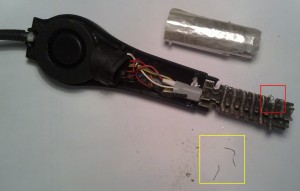
Actually, there was also something else. Two small pieces of wire stuck in the middle of the resistor coil, shorting some of the turns. And at one point, coincidentally exactly where one of the two extraneous metal wires was shorting the coil, the coil was melted, resulting in an open circuit.

fail-large

In the picture above you can see in the red square the point where the heating element was broken, and in the yellow square the two pieces of extraneous metal wire that I removed from the heater coil.

The next question is: did those two pieces of wire end up there as a mistake, or were they put there on purpose to cause hot spots in the heater so as to make it fail prematurely? Is this a case of planned obsolescence? In any case I’m not going to buy Atten branded stuff again.

Thermopiles and tunnel diodes: a candle powered LED

March 25, 2016

This is just a small project that I’ve been doing to explore some not so well known technologies. The goal is simple: use the heat of a candle to turn on an LED. Actually making a device that does this function turned out to be not that simple, though.

Part 1: The Thermopile

To generate electricity out of a candle flame, I decided not to go the obvious route of buying a TEG, but instead to try building its ancestor, the thermopile.
A TEG, or thermoelectric generator is a device made of a number of semiconductor junctions in series that generate a small voltage when a temperature difference is applied to them. They are essentially the same in construction as the more common TEC, or thermoelectric cooler, that can be found easily on ebay.
The main reason why I have decided not to use them, is that TECs/TEGs get damaged at temperatures above 150°C or so. Since the flame of a candle is well above that temperature, I would need to come up with a way to reduce the flame temperature to a usable value.
A thermopile is a series arrangement of thermocouples. It works in the same way as a TEG, but uses metal junctions instead of semiconductor ones. Thus, it is more rugged and can easily withstand higher temperatures.
At first, I tried making a thermocouple out of materials I had at home, namely copper wire and nichrome wire, but the results were very poor, as I could only get a few millivolts out of it when exposed to a flame. So, I ordered a K thermocouple to cut its wires into pieces and experiment with thermopiles.

00-thermocouple

This is what remains of the thermocouple after the experiments. I’m sure it still works if I solder back the wires to the connector.

01-first-thermopile

This is my first thermopile. It was built by cutting two 4cm pieces of thermocouple cable, straightening the wires -as they were twisted together- stripping the insulation and twisting the chromel and alumel in order to make the hot junction. I would have tried welding them together, but I lack the necessary equipment. The cold junction between the two thermocouples can simply be soldered, as it doesn’t have to withstand hundred of degrees.
When exposing both hot junctions to a candle flame, I got around 65mV, that’s promising.

02-second-thermopile

This is my second attempt at making a thermopile. I used mica sheets above and below to provide some mechanical strength and try protecting the twisted hot junctions from the flame. My fear was that since the metal is just twisted and not welded, if it oxidizes due to the heat, it may no longer form an electrical connection.
This design turned out to be a bad idea, though. Despite having three thermocouples in series, I could not get more than 50mV out of it. The main reason is most likely that the mica introduces a thermal resistance between the flame and the junctions, so the temperature they reach is lower.

04-third-thermopile

After the failed attempt, it was clear that to work well a thermopile requires the metal to be exposed to the flame. Having learned that, the next step was to make a working device and not just a test. I wanted to get around 200mV out of it (see the next part for the reason), so that means 6 thermocouples in series. After spending some time thinking how I could make a design with 6 thermocouples close together enough to be heated directly by a single candle flame, this is what came out. I used four mica spacers to prevent shorting, and epoxy on the outer spacers to provide some mechanical robustness to the design.

I also tried to do some computations to figure out what could be expected out of such a device. The expected voltage is three times the one I got out of the first test, about 200mV. That means around 33mV per thermocouple.
Estimating the current is a little bit more difficult. The seebeck effect theory seems to focus on a voltage difference being generated, but does not mention current. So I guessed that what limits the current flow is just the resistance of the wires. Looking up the resistivity of chromel and alumel resulted in those formulas:
chromel 0.706uohm/m (1+0.00032*T)
alumel  0.294uohm/m (1+0.00239*T)
The resistance depends on temperature, and given that the hot junction reaches hundred of degrees, it likely can’t be neglected.
According to the K thermocouple curves, a 33mV voltage means around 700°C of temperature difference. As the cold junction does get a little bit hot as well, an educated guess may be 750°C for the hot junction, and 50°C for the cold one. To simplify computations, I assumed that temperature varies linearly along the wire, leading to an average temperature of 400°C. Considering that the wires have a 0.3mm diameter, and are 4.5cm long, a single thermocouple has an estimated resistance of 0.9ohm, and the entire arrangement 5.4ohm.
This means a 37mA short circuit current. The maximum power that can be expected out of this device is thus half of the open circuit voltage times the short circuit current, or around 3.7mW.

05-short-circuit-current

Measuring the short circuit current of a device outputting such a low voltage is not easy. A simple multimeter has a burden voltage in the same order of magnitude as the open circuit voltage (~200mV), introducing a significant error in the measure. As I don’t have a uCurrent, I settled for using a short loop of 26AWG copper wire as a low value shunt resistance, and using a millivoltmeter with 0.1mV resolution. Since the resistance of the shunt is unknown, it was first measured using a known current, and resulted to be 0.035ohm.
In the picture above we can see the reading, which is 1.7mV (the millivoltmeter lacks a decimal point). The short circuit current is 48mA, nearly 10mA higher then predicted. This was due to the wire having a lower resistance than the one computed before.

06-open-circuit-voltage

An open circuit test showed I got 178mV out of it. Not quite 200mV as I hoped, but close enough. In the picture you can also see the wire loop used as low value shunt resistor. So, with ~180mV open circuit and ~48mA short circuit, assuming the best power transfer to the load, this thermopile would produce around 4.3mW.

Part 2: DC-DC converter

Up until know I had fun building a working thermopile, but how to turn on an LED with it? LEDs need different voltages to turn on, with red ones requiring just 1.8V, and blue ones going as high as 3.6V. Thus, at least 55 thermocouples in series are required to directly power an LED. A different approach is apparently required.

The issue is, there aren’t many ways to build a DC-DC converter that works with just a few hundred millivolts. A blocking oscillator, also commonly known as joule thief can be designed to operate at just 200mV, if using a transistor with a low enough VCE|sat, but still requires 700mV to bias the base when first powered up. MOSFETS are even worse, even the best ones require more than 1V to their gate before thay do anything.

Although there are energy harvesting ICs nowadays that are designed to step up very low voltages, I didn’t want to go the IC route. Given the experimental nature of this project, I wanted to stay close to physics rather than using a black box IC that does what I need but leaves me with little knowledge of what’s going on inside. Also, I didn’t happen to have any energy harvesting IC lying around, but I had something else that would do the trick.

A while ago I watched a video about tunnel diodes. They are quite unlike conventional diodes, as for voltages between around 0.18V and 0.8V they have a negative resistance region, where current decreases as voltage increases. This means that an oscillator can be made with them, operating at just 180mV. From there, a transformer can be used to step up the voltage. An inverter circuit can thus be made with just two components: a tunnel diode and a transformer. Such a circuit appears to be little known, but is very old. I found it at page 104 in this RCA book from 1963.

07-dc-dc-converter

The tunnel diodes I have are АИ301Г, rated at 10mA peak current. For the transformer, I repurposed a toroidal core out of a broken CFL neon lamp. I measured the inductance factor in order to get predictable inductance values, and it is AL=700nH. I wanted the device to oscillate at just a few tens of kilohertz, so the primary was chosen to have a rather high 500uH inductance. Doing the math, 27 turns are needed. I used 30AWG wire. The secondary was made out of 95 turns of AWG36 wire.

waveforms

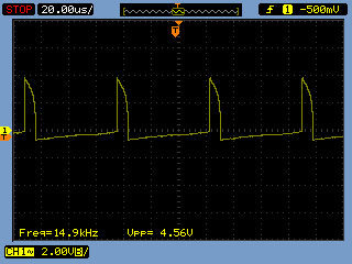
This is the output of the secondary. 4.5V peaks at 15KHz.

08-working.jpeg

Yes, it does turn on a high brightness LED. Success.

curves

To characterize a bit more the output, I rectified the secondary of the transformer with a BAT42 diode and a 1uF capacitor. Applying different load resistors, here are the curves of the output. The maximum power point is 180uA at 1.8V, or 324uW. Quite a bit lower than expected. This is most likely because the thermopile voltage is only 180mV, which is the same as the tunnel diode peak voltage. So, the oscillator barely turns on. With 250 to 300mV the power output would probably be higher. Also, a disadvantage of the tunnel diode oscillator is that the maximum output power is limited by the diode peak current, which is just 10mA. To get more power, you need a bigger diode.

Conclusions
Here’s a video of the thermopile working.

The experiment was a success. Maybe someday I’ll try to improve the efficiency by making a 8 element thermopile, but still I’ll be limited by the tunnel diode peak current. Despite the RCA book mentions 1, 10 and even 100A tunnel diodes, those 10mA diodes were the best I could find. Maybe I could try a push-pull configuration with two tunnel diodes, or use the tunnel diode to kickstart a joule thief, who knows.

Miosix 2.0 code size

May 4, 2014

If you’ve tried the new Miosix 2.0 recently, you may have noticed that compiling an hello world without tweaking the build options results in a code size of around 90KB for the kernel plus the hello world program. This appears to be a big step up with respect to Miosix 1.6, but is due to the fact that more features are enabled by default, as well as due to the completley rewritten filesystem subsystem with support for advanced features such as multiple mountpoints, unicode in file names DevFs etc.

However, the kernel is very modular and the code size is only limited by the features you need. This quick guide shows how it is possible to bring the size of Miosix 2.0 down to around 6KB by disabling features you may not need. This is the same size of a minimal configuration of Miosix 1.6.

Miosix 2.0beta1 released

April 13, 2014

If you’re watching Miosix’s git repository, you probably noticed that in the last year most commit were done in the testing branch, but until now no official information was available on how to use the testing branch.

Today Miosix 2.0beta1 has been officially released, together with changes to the Miosix website, including a wiki.

A short list of changes introduced in Miosix 2.0:

  • Upgraded GCC compiler to 4.7.3
  • Support for hardware floating point operations in Cortex M4 (thanks to the new GCC and to an updated context switch code)
  • Improved atomic operations, which speeds up mutex locking
  • Improved memory profiling to return more detailed heap statistics
  • Completely rewritten the filesystem code, with better POSIX compliance, support for multiple mountpoints, Unicode in file names, and in-memory filesystems including DevFs like on Unix machines
  • Experimental multiprocess environment with memory protection and supporting loading code at runtime (work in progress)
  • Improved serial port drivers with DMA support for reading and writing
  • More board support

Check out the Miosix wiki.

Broken mac power supply

September 1, 2013

One of my computers, the one I use for web browsing is a Mac. Despite that, I’ve installed Linux on it and use it instead of Mac OS almost all the time, but this is another story.

Anyway, a few days ago, my Mac simply stopped charging. I was on holiday, so I had to wait until I got back home to troubleshoot what happened. Measuring the output voltage resulted in a zero volt reading, so I opened it up.

macbug-big

Inside I found a burnt resistor, and a blown fuse. The resistor appears to be the bleeder resistor in parallel with the input capacitor. It has likely failed resulting in a short circuit, and the fuse blew.

Now, Apple chargers are usually touted for their high quality compared to cheap chinese clones, however I wonder who thought that putting a tiny 0805 resistor in parallel on a high voltage line was a good idea…

Sure, the charger worked reliably for five years (I bought the Mac in 2008), and failed in a rather safe way (mainly thanks to the fuse) but still I think this failure mode could have been somehow forecasted, also considering that this is not the first time I see it. The other time was in an inverter, a device that produces a 230VAC output given a 12VDC input. The step-up circuit had a diode bridge rectifier, a capacitor, and a tiny 1/10W resistor (it was entirely through-hole, no SMD). One day I turned the inverter on, and heard a loud pop and a flash of light through the heat vents.

In the meantime I had to find a way to somehow power the Mac again. I cut the power cable and connected it to the only device I had lying around that could produce 16.5V at 4.6A… a cheap chinese power supply. That’s ironic, to say the least…

macfix

tea-time turns your smartwatch back into a watch… and a 3D rendering engine

August 24, 2013

A while ago this post caught my attention on Hackaday. Sony relased some hardware specifications of its smart watch, and invited people to hack it and write custom firmwares. It wasn’t the first time I’ve heard about that smart watch, as I had alreay found (thanks Daniel) a teardown of it.

The author of the teardown actually was disappointed by finding a microcontroller instead of a Linux capable processor in the watch, but being used to microcontrollers, this was no problem. Also, Sony didn’t put into the watch a tiny 8bit microcontroller, but instead chose an ARM running at 120MHz, with 128KB of RAM and 1MB of FLASH. That’s a lot to work with.

However, before Sony’s move towards openness, I wasn’t that much interested in the watch, as it takes too much time compared to the one I have available to reverse engineer a firmware to understand how to write drivers for the display, touchscreen etc. After reading that news on Hackaday, and looking at the documentation, though, I ordered the watch straight away.

This turned out to be, at least partially, a bad move. This is because if looked on the surface the documentation on Sony’s site seemed sufficient to write a custom firmware, as it says on which GPIO pins devices are connected, there’s the part number for the display controller, and some source code for driving the touchscreen. When looking deeper, though, many parts were missing. For example, searching the display controller datasheet on a search engine resulted only in links to the site of the company who produce it – and no datasheet. Also, certain parts of the watch’s hardware were missing entirely from the documentation. For example, it was later found out that the watch has a power management unit that controls battery charging and turns the watch off under software control, but this is entirely missing from the documentation.

Shortly after, however, always on Hackaday, a post showed an Arduino-like toolchain to write sketches for the smart watch. Personally, I am not very fond of the Arduino. Probably since I’m used to programming microcontrollers using an RTOS (Miosix), having to fit all my code logic in the loop() function seems unnatural to me. Also, one of the few things I like about the Arduino: openness here was missing, as no hardware schematics of the watch have ever been released by Sony.

At least the availability of the Arduino toolchain gave me a code base to look at to understand how the watch works, it’s way better than reversing the binary of the original firmware! Quickly, I understood that the Arduino firmware was written by someone who had much more documentation than the one which is publicly available. For example, the file system.c mentions in the comments “SONY’S NAME” for each GPIO pin. Clearly they had access to the original source code of the watch. It’s by reading that code that I came to know about the existence of the power management unit.

The Arduino code, and in particular its comments, filled the gap left open by the lack of documentation and helped a lot in the process of porting the Miosix kernel and the Mxgui library to the watch, which was my end goal.

Enough talk, let’s start with a demo. Here is a simple but functional firmware, called tea-time, that turns the smart watch into… a watch. To test the hardware’s performance I ported a simple 3D rendering engine for Mxgui to the watch, it draws in real time the famous utah teapot, resulting in quite an original watch face.

solidwireframe

There’s also a video showing the smoothness of the rendering.

Needless to say, the firmware is entirely free software/open source, and can be found in the examples directory of the mxgui library. For trying it out without the need to compile it, the compiled firmware is here.Although it’s just a preliminary version, and there’s still work to do, it already provides a battery status indicator and dynamic display brightness adaptation based on ambient light, as well as a 30s timeout after which the display turns off to save power.

For developers

The code is written in C++ as a multithreaded application for Miosix, using the POSIX threading API. There’s also a simulator for the GUI to help design the user interface without the need to flash the watch every time to see how a modification looks like.

sim1sim2

In the future I’ll probably add a tutorial on how to set up the miosix/mxgui environment, how the optimized video driver for the smart watch works and how the rendering engine works. There are a lot of tricks in there…

Update 25/08/2013

The link to the firmware now points to a new version. The previous one had a bug in the power saving code, causing the battery to last only one day. This one should be better.

Update 1/9/2013

The new firmware did actually fix the battery issue. It now lasts 6 days.

Synchronization primitives in Miosix

October 6, 2012

A small and backwards compatible change in Miosix 1.61 made me think about low-level synchronization primitives, and the fact that doumentation on how to use them was lacking. So, here’s a page dedicated to this topic.